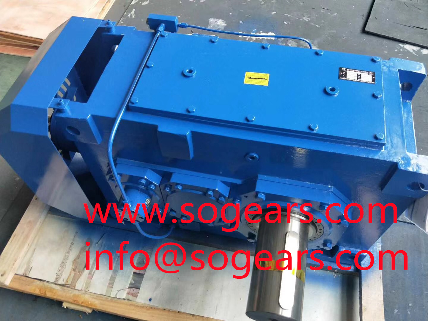
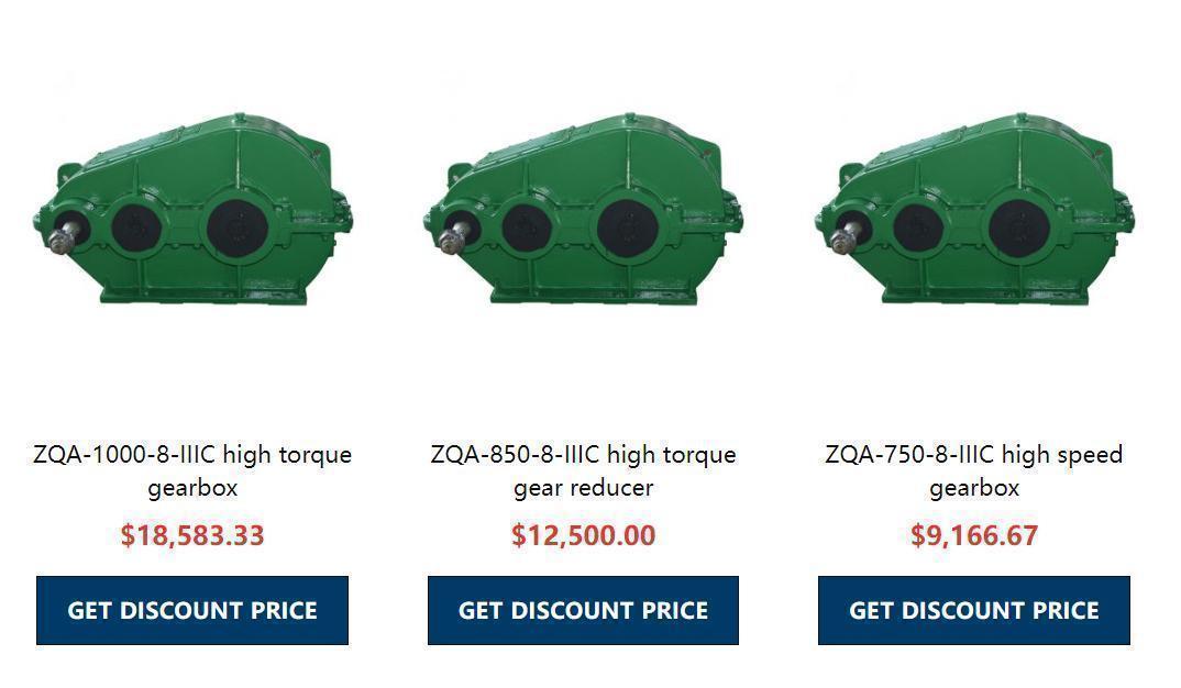
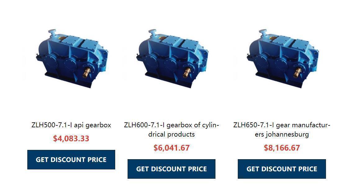
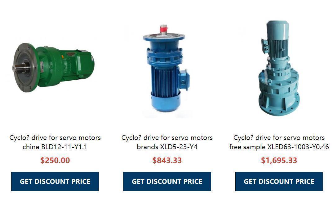
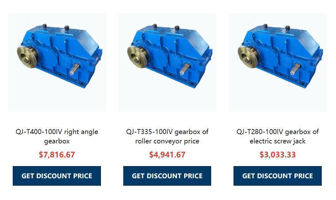
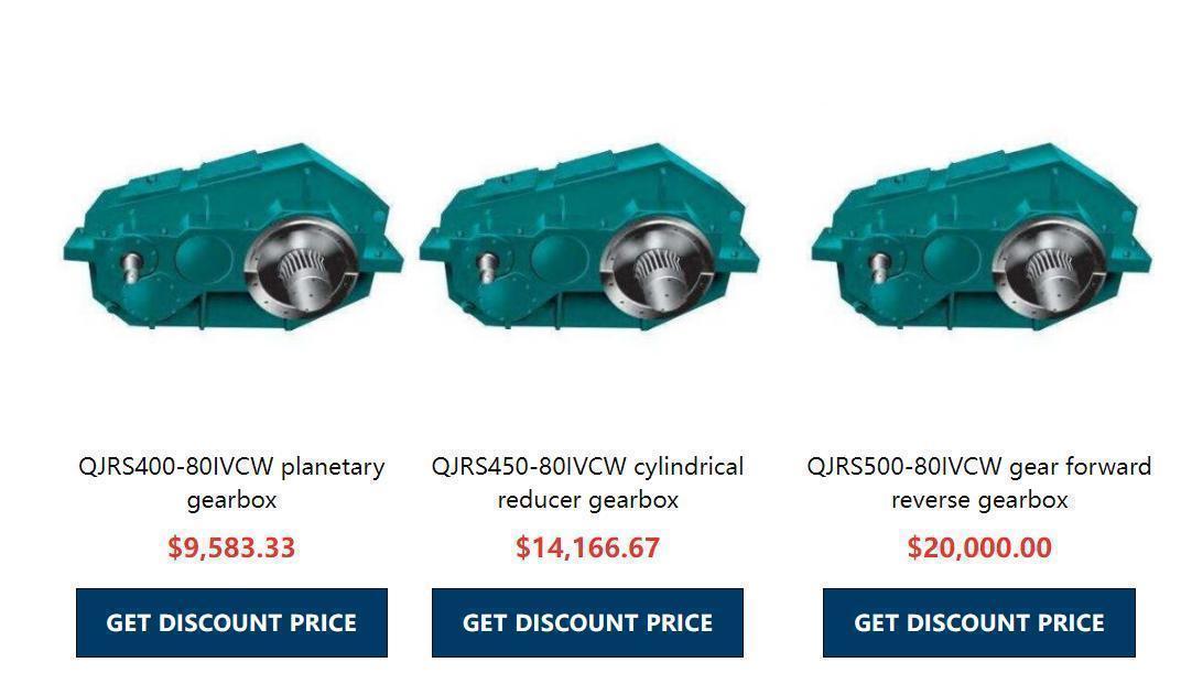
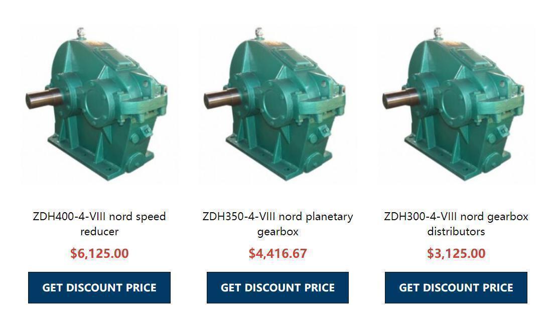
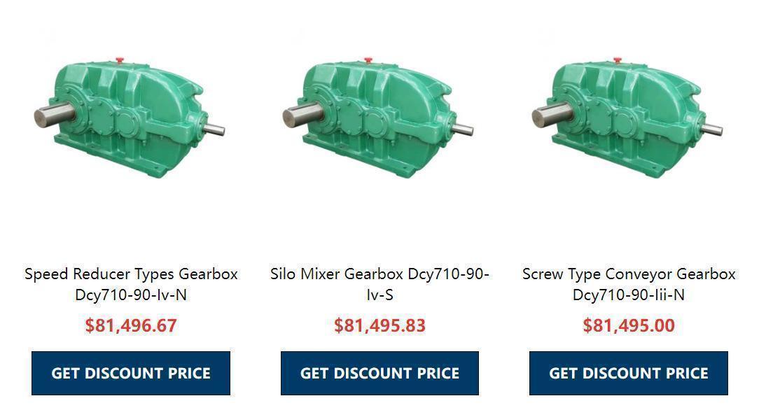
50-1200Nm वर्म गियर स्पीड रिड्युसर मोटर गियरबक्स उच्च परिशुद्धता हेलिकल गियर रेड्युसर गियरबक्स
Distribution of transmission ratio of micro cycloidal pin gear reducer As the maximum transmission ratio of single-stage bevel gear reducer does not exceed 10, when the total transmission ratio is required to exceed this value, two-stage or multi-stage bevel gear reducer shall be used. At this time, the reasonable distribution of transmission ratios at all levels should be considered, otherwise it will affect the size of the bevel gear reducer's overall dimensions and whether the bearing capacity can be fully utilized. The transmission ratio can be distributed according to the following principles according to different use requirements:
(1) Make the bearing capacity of all levels of transmission nearly equal;
(2) Minimize the overall dimension and mass of bevel gear reducer;
(3) Make the transmission have the minimum moment of inertia;
(4) Make the oil immersion depth of big gears in all levels of transmission approximately equal
The structure of CVT is mainly composed of gear (or worm), shaft, bearing, box, etc. The box must have sufficient rigidity. In order to ensure the rigidity and heat dissipation of the box, reinforcing ribs are often made on the outer wall of the box. In order to facilitate the manufacture, assembly and use of the bevel gear reducer, a series of accessories are also set on the bevel gear reducer, such as inspection holes, air vents, oil dipstick or oil level indicator, hooks and cap screws.
The transmission ratio of this series is fixed, but in engineering practice, some working machines often need to work at several different speeds, so it is necessary to adjust the transmission ratio between the prime mover and the working machine at any time according to the use requirements.
Working principle: depending on friction transmission, change the output radius of the driving and driven parts to achieve no change in the transmission ratio. The transmission ratio is fixed, but in engineering practice, some working machines often need to work at several different speeds, so it is necessary to adjust the transmission ratio between the prime mover and the working machine at any time according to the use requirements.
Type: Stepped transmission - the transmission of a stepwise transmission can only be graded through the control mechanism according to the established design requirements, and the transmission ratio of a stepless transmission - the stepless transmission can be changed steplessly within the predetermined design range.
50-1200Nm वर्म गियर स्पीड रिड्युसर मोटर गियरबक्स उच्च परिशुद्धता हेलिकल गियर रेड्युसर गियरबक्स
The structure of WB100 miniature cycloidal pin gear reducer mainly consists of the distribution of the transmission ratio of gear (or worm), shaft and bevel gear reducer. As the maximum transmission ratio of single-stage bevel gear reducer does not exceed 10, when the total transmission ratio is required to exceed this value, two-stage or multi-stage bevel gear reducer shall be used. At this time, it is necessary to consider the reasonable distribution of transmission ratios at all levels. Otherwise, it will affect the size of the overall dimensions of the bevel gear reducer and whether the bearing capacity can be distributed as the transmission ratio of the stepless transmission. As the maximum transmission ratio of the single-stage bevel gear reducer does not exceed 10, when the total transmission ratio is required to exceed this value, the two-stage or multi-stage bevel gear reducer should be used. At this time, the reasonable distribution of transmission ratios at all levels should be considered, otherwise it will affect the size of the bevel gear reducer's overall dimensions and whether the bearing capacity can be fully utilized. The transmission ratio can be distributed according to the following principles according to different use requirements:
(1) Make the bearing capacity of all levels of transmission nearly equal;
(2) Minimize the overall dimension and mass of bevel gear reducer;
(3) Make the transmission have the minimum moment of inertia;
(4) Make the oil immersion depth of big gears in all levels of transmission approximately equal.
The reducer is a relatively precise machine, which is used to reduce speed and increase torque. In some places, it is also used for speed increase, called speed increaser. It is generally used for transmission equipment with low speed and large torque. The power of motor, internal combustion engine or other high-speed operation is reduced by meshing the gear with fewer teeth on the input shaft of the reducer with the big gear on the output shaft. Ordinary reducers also have several pairs of gears with the same principle to achieve the ideal reduction effect. The ratio of the number of teeth of big and small gears is the transmission ratio.
There are many types, varieties and types of reducers, and there are more than 40 kinds of reducers that have been formulated as the national standard. The reducer is classified according to the adopted gear tooth profile and tooth profile curve; The type of reducer is the reducer with different structure designed according to the needs of utilization; The type of reducer is a reducer with different characteristics designed on the basis of basic structure according to tooth surface hardness, transmission stages, shaft type, assembly type, installation type, connection type and other factors.
Speed ratio=motor output revolutions ÷ reducer output revolutions ("speed ratio" is also called "transmission ratio") 1. Know the motor power, speed ratio and service factor, and calculate the reducer torque as follows: reducer torque=9550 × Motor power ÷ motor power input revolutions × speed ratio × Service factor 2. Know the torque, reducer output revolutions and service factor, and calculate the motor power required for the reducer as follows: motor power=torque ÷ 9550 × Motor power input revolutions ÷ speed ratio ÷ service factor It has many kinds, different models, and different types have different uses.
50-1200Nm वर्म गियर स्पीड रिड्युसर मोटर गियरबक्स उच्च परिशुद्धता हेलिकल गियर रेड्युसर गियरबक्स
There are many kinds of reducers, which can be divided into gear reducers, worm gear reducers and planetary gear reducers according to the transmission type; According to different transmission stages, it can be divided into single-stage and multi-stage reducers; According to the gear shape, it can be divided into cylindrical gear reducer, bevel gear reducer and bevel cylindrical gear reducer; According to the layout of transmission, it can be divided into deployable, split flow and coaxial reducers. The following are common gear reducer classifications:
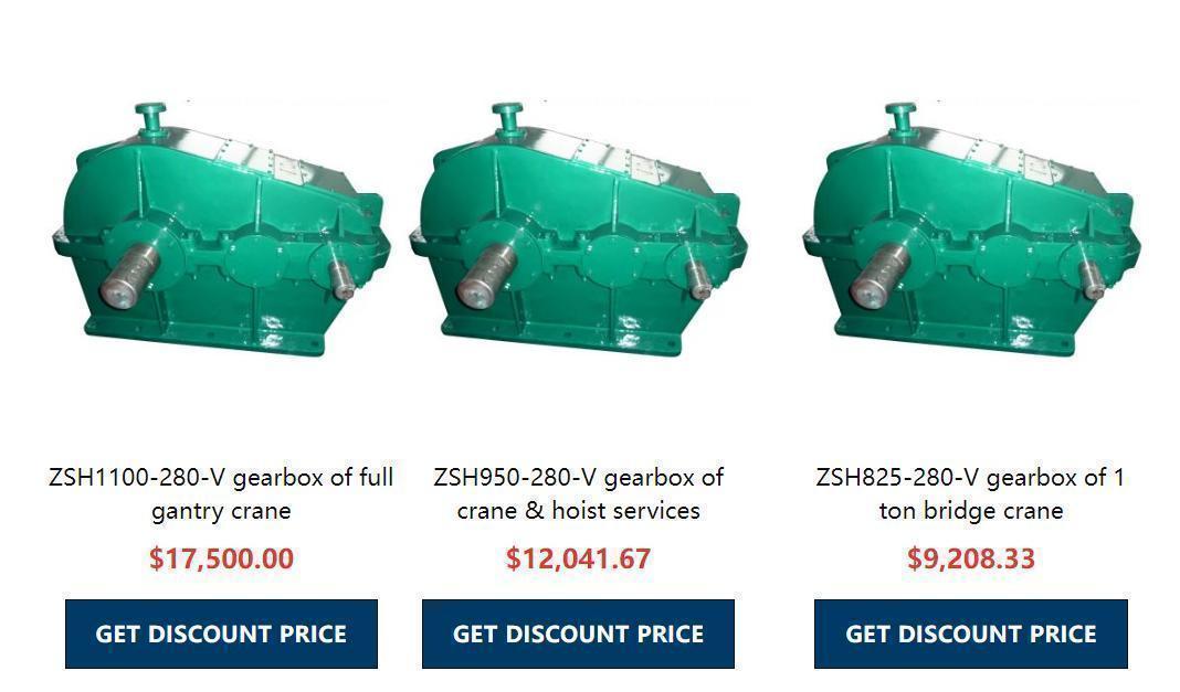
1. Cycloidal reducer 2, hardened cylindrical gear reducer 3, planetary gear reducer. 4. Soft tooth surface reducer 5, three ring reducer 6, crane reducer 7, worm gear reducer 8, hard tooth surface reducer 9, stepless speed reducer
Industrial robot is one of the most advanced equipment in the development of industrial intelligence and the application of artificial intelligence technology. Industrial robots need to have accurate movement and positioning, as well as multi degree of freedom and multi speed operation, which is also the technical difficulty difference between multi joint robots and non joint robots to a certain extent. Articulated robots can do a lot of work similar to automatic assembly, painting, transportation, welding, etc., and these work require different speed ratios to coordinate the entire operation process to achieve accurate application and effect. At this time, reducers are needed.
RV reducer is one of the most common reducers in industrial robots at present. The working principle of RV reducer is composed of the first stage involute cylindrical gear planetary reducer and the second stage cycloidal pin gear planetary reducer. The driving sun gear is connected with the input shaft. If the involute central gear rotates clockwise, it will drive three planetary gears arranged at 120 ° to rotate counterclockwise while rotating around the central gear axis. The three crank shafts are connected with the planetary gears and rotate at the same speed. Two cycloidal gears with a phase difference of 180 ° are hinged on the three crank shafts and mesh with the fixed needle wheels. When their axes rotate around the needle wheel axis, It also rotates in the opposite direction, i.e. clockwise. The output mechanism (i.e. the star carrier) is driven by three pairs of crank shaft support bearings mounted on it, and transmits the rotation vector on the cycloidal gear at a speed ratio of 1:1.
50-1200Nm वर्म गियर स्पीड रिड्युसर मोटर गियरबक्स उच्च परिशुद्धता हेलिकल गियर रेड्युसर गियरबक्स
RV transmission is a new type of transmission, which is developed on the basis of traditional pin cycloidal planetary transmission. It not only overcomes the shortcomings of general pin cycloidal transmission, but also has a series of advantages such as small volume, light weight, large transmission ratio range, long life, stable accuracy, high efficiency, and stable transmission. More and more attention has been paid at home and abroad. RV reducer is composed of cycloidal pin wheel and planetary support, which is widely used in industrial robots, machine tools, medical testing equipment, satellite receiving systems and other fields due to its small size, strong impact resistance, large torque, high positioning accuracy, small vibration, large deceleration ratio and many other advantages. It has much higher fatigue strength, stiffness and life than the harmonic drive commonly used in robots, and the return error accuracy is stable, unlike the harmonic drive, which will significantly reduce the motion accuracy with the increase of service time. Therefore, RV reducer is widely used for high-precision robot transmission in many countries in the world. Therefore, the RV reducer will gradually replace the harmonic reducer in the advanced robot transmission.
After understanding the working principle of RV reducer, we can find that when the RV reducer is decelerating at the first stage, it is the total reduction ratio obtained by multiplying the reduction ratio generated by the interaction of the crank shaft, input gear and spur gear, and the second reduction ratio generated by the interaction of eccentric shaft, needle roller bearing and RV gear. Therefore, it is possible to achieve a large reduction ratio range to ensure sufficient torque to complete higher intensity work for industrial robots.
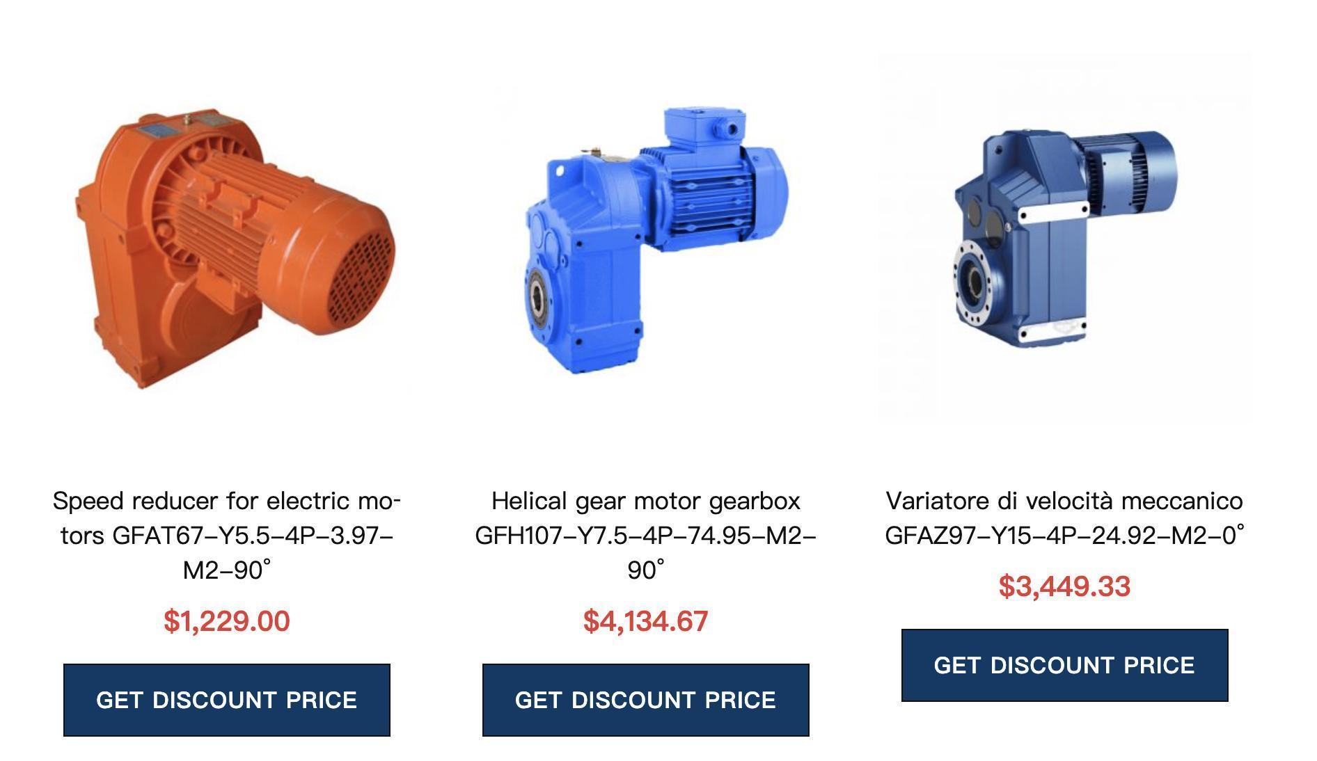
Product overview of F series parallel axis helical gear reducer motor: 1. F series parallel axis helical gear reducer motor adopts modular design and can be combined according to customer requirements,
2. The reducer is driven by an involute planetary gear, making rational use of internal and external meshing and power distribution,
3. All gears are carburized and quenched to obtain a high hard wear-resistant surface. After heat treatment, all gears are ground to reduce noise and improve the efficiency and service life of the whole machine.
4. The gear reducer is characterized by light weight, small volume, large transmission ratio range, high efficiency, smooth operation, low noise, and strong adaptability. Reducers are widely used in metallurgy, mining, hoisting and transportation, power, energy, building materials, light industry, transportation and other industrial sectors.
प्रदर्शन विशेषताहरु:
1. F series parallel shaft helical gear reduction motor adopts involute planetary gear transmission, and makes rational use of internal and external meshing and power distribution. Therefore, it has the characteristics of light weight, small volume, large transmission ratio range, high efficiency, smooth operation, low noise, strong adaptability, etc
2. The box body is made of ductile iron, which greatly improves the rigidity and seismic resistance of the box body.
3. Input mode: concentric shaft input, helical gear input, bevel gear helical gear input, bevel gear input.
4. Output mode: internal spline type, hollow shaft shrink disk type, external spline type, solid shaft flat key.
5. Installation type: horizontal installation, vertical installation, torque arm installation.
6. Modular design is adopted, which can be changed and combined according to customer requirements.
7. Combined with R series and K series, higher speed ratio can be obtained.
प्राविधिक मापदण्डहरू:
Speed ratio range: 3.81~281.71 for basic type, 31434 for F/R combination type
Torque range: 200 ~ 18000 Nm
उर्जा दायरा: ०.०0.18 ~ २२ किलोवाट
संरचनात्मक रूप:
F - shaft extension type, foot installation FF - shaft extension type, flange installation
S - shaft input FA shaft mounted connection
KAF shaft mounted, flange mounted
Fast query list of F series reduction motor model:
F37、F47、F57、F67、F77、F87、F97、F107、F127、F157
FA37、FA47、FA57、FA67、FA77、FA87、FA97、FA107、FA127、FA157
FF37、FF47、FF57、FF67、FF77、FF87、FF97、FF107、FF127、FF157
FAF37、FAF47、FAF57、FAF67、FAF77、FAF87、FAF97、FAF107、FAF127、FAF157
FAZ37、FAZ47、FAZ57、FAZ67、FAZ77、FAZ87、FAZ97、FAZ107、FAZ127、FAZ157
50-1200Nm वर्म गियर स्पीड रिड्युसर मोटर गियरबक्स उच्च परिशुद्धता हेलिकल गियर रेड्युसर गियरबक्स
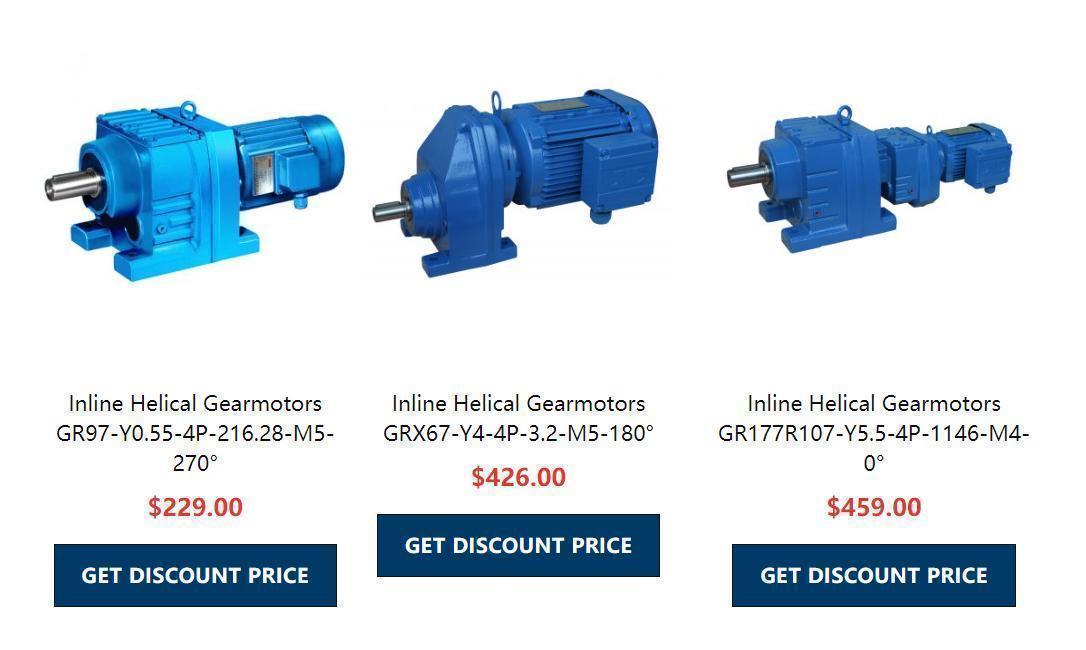
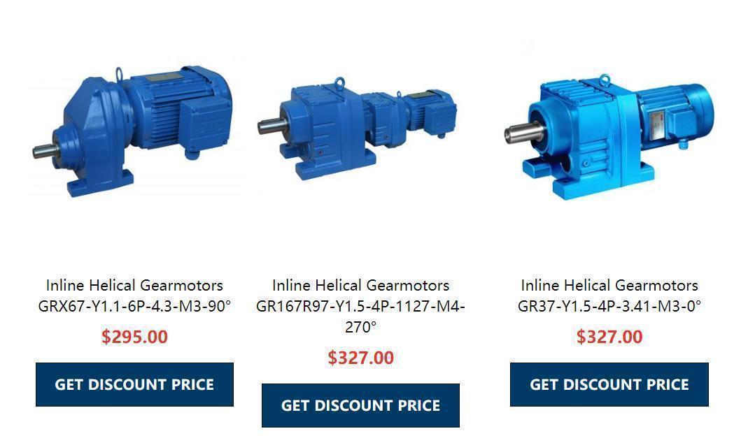
आर श्रृंखला पेचदार गियर रिडुसर
उत्पादन अवलोकन:
1. R series helical gear reducer with hard tooth surface features low vibration, low noise and high energy saving;
2. आर श्रृंखला रिड्यूसर अन्तर्राष्ट्रिय रूपमा उन्नत प्रसारण मेकानिकल मोडेलको साथ Shueide समूह द्वारा अनुकूलित छ;
3. R श्रृंखला रिड्यूसर उच्च-गुणस्तरको जाली स्टील, स्टिल कास्ट आइरन बक्सबाट बनेको छ, र गियर सतह उच्च-फ्रिक्वेन्सी ताप उपचारको अधीनमा छ;
4. कडा दाँत सतह संग R श्रृंखला हेलिकल गियर रिड्यूसर कम ऊर्जा खपत र उच्च प्रदर्शन छ। आर कोएक्सियल हेलिकल गियर रिड्यूसरको दक्षता 95% भन्दा बढी छ;
5. सटीक मेसिनिङ पछि, शाफ्ट समानान्तर र स्थिति असर आवश्यकताहरू सुनिश्चित गर्न, हेलिकल गियर ट्रान्समिशन एसेम्बली बनाउने रिड्यूसर विभिन्न प्रकारका मोटरहरूसँग सुसज्जित छ, जुन इलेक्ट्रोमेकानिकल एकीकरणमा जोडिएको छ, पूर्ण रूपमा रेड्यूसर उत्पादनहरूको गुणस्तर विशेषताहरूको ग्यारेन्टी गर्दै।
प्रदर्शन विशेषताहरु:
1. विशेष रूपमा मिश्रणको लागि डिजाइन गरिएको RM श्रृंखलाले ठूलो अक्षीय बल र रेडियल बल सहन सक्छ।
2. स्थापना विधि: खुट्टा स्थापना, ठूलो र सानो flanges संग फ्ल्यान्ज स्थापना, छनोट गर्न सजिलो।
3. ठोस शाफ्ट आउटपुटको लागि, औसत दक्षता दोस्रो चरणको लागि 96%, तेस्रो चरणको लागि 94%, र R/R संयोजनको लागि 85% छ।
4. अभिन्न कास्टिङ बक्स अपनाईएको छ, र बक्स संरचना राम्रो कठोरता छ, जो शाफ्ट को बल र असर को सेवा जीवन सुधार गर्न सजिलो छ।
5. सानो अफसेट आउटपुट, कम्प्याक्ट संरचना, बक्स स्पेसको अधिकतम प्रयोग, एउटै बक्समा माध्यमिक र तृतीय।
प्राविधिक मापदण्डहरू:
टोक़ दायरा: R आधारभूत प्रकार 85 ~ 18000 Nm, RX प्रकार 20 ~ 1680 Nm
पावर दायरा: R आधारभूत प्रकार 0.18 ~ 160 kW, RX प्रकार 0.18 ~ 132 kW
गति अनुपात दायरा: R आधारभूत प्रकारको लागि 3.33 ~ 289.74, RX प्रकारको लागि 1.3 ~ 8.65, R/R संयुक्त प्रकारको लागि 27001
संरचनात्मक रूप:
आर: शाफ्ट एक्सटेन्सन फुट स्थापना आरएफ: फ्ल्यान्ज स्थापना
आर... एफ: फुट फ्ल्यान्ज स्थापना RM: विस्तारित असर बक्स संग फ्ल्यान्ज स्थापना
RX: single-stage footing installation RXF: single-stage flange installation.
